Import a DWG / DXF
What is a DWG file? - A DWG file is a proprietary binary file format used for storing two and three dimensional design data and metadata. It is the native format for several CAD packages including AutoCAD, DraftSight, IntelliCAD (and its variants), Caddie and Open Design Alliance compliant applications.
What is a DXF file? - A DXF file is a Drawing Interchange Format, or Drawing Exchange Format which is a CAD data file format developed by Autodesk for enabling data interoperability between AutoCAD and other programs.
Most exhibition venues provide DWG/DXF files for you to use so that you can plan your exhibition accurately. EFD will import these files so you can then use the unique functions of EFD to plan out your floorplan. Once you have finished your floorplan you can then export it back to DWG/DXF if the venue requires it. Please note that we have many venue drawings already imported and ready to use so please contact us first before importing your DWG/DXF.
DWGs exported from EFD
WARNING: Don't import a DWG that was exported from EFD to carry on working on a plan. An exported DWG doesn't contain your EFD stands and stand information. Open the original EFD file instead.
You can import a DWG or DXF into EFD using a DWG import template, then place and scale it.
Import a DWG/DXF
TIP: Before importing a DWG, check our venue template database. The venue may already be available as a ready-made EFD template, which saves you importing and scaling it yourself.
-
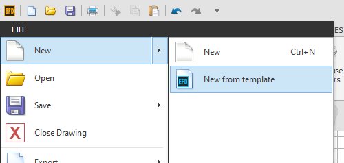
Select the 'New from template' option from the FILE > New menu.
-
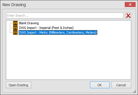
The following dialog will now appear. Select the DWG import template that matches the units your DWG was drawn in: 'DWG Import - Metric (Millimeters, Centimeters, Meters)' or 'DWG Import - Imperial (Feet & Inches)'. For this example we will be importing a DWG that was drawn using metric measurements, so we will select the metric template.
NOTE: Most venue DWGs will have been drawn using metric measurements unless they are from the USA.
-
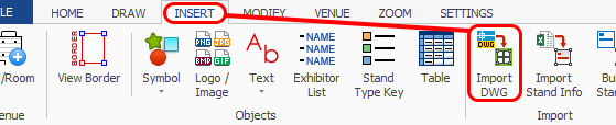
Click on the 'Import DWG' button which is located on the INSERT ribbon. You will now need to locate the DWG file on your computer that you want to import, then click 'Open'
-
The below message box will appear.
Click continue to carry on with the import.

-
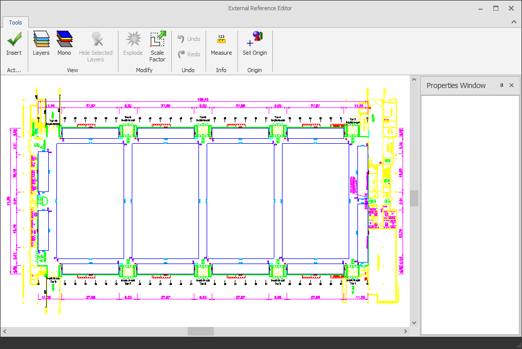
A window will now appear showing you a preview of the DWG/DXF to import.
-
If you want to, you can now delete entities you do not want/need or manage the layers to show/hide as required. When you are ready, click the Insert button in the top left.
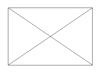
IMPORTANT NOTE: If you cannot see anything on the end of you mouse cursor after clicking INSERT, you will need to ZOOM IN using the wheel on your mouse until you can see a box with a cross in it, this is the placeholder for your DWG (see image below).
-
You now need to specify where you want the DWG/DXF positioned on-screen so, just click on the screen to place the DWG/DXF.
After placing the DWG/DXF you will need to specify the rotation of it and we recommend keeping it at 0 degrees so, to do this press F6 (Angle Lock) on your keyboard and move your mouse to the right, then just click.
TIP: If you need to move the DWG/DXF afterwards, just select it and then move it by clicking on the Red node or by using the Move command.
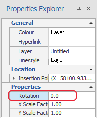
TIP: If you inserted the DWG/DXF at the wrong angle, you can change the angle by selecting the inserted DWG/DXF and then editing the Rotation in the Properties Explorer as shown below. If you cannot see the Properties Explorer, click here.
-
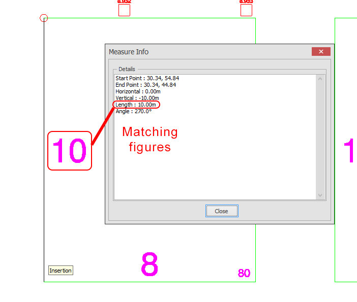
Now your DWG/DXF has been inserted you need to zoom into the drawing and check a measurement to make sure it is correct. On the example below you will see that there is a 10 x 8 stand on the drawing I imported so I can just measure that using the measure tool to make sure it reads in metres.
Using the measure tool click on the point you want to measure from and then click on the point you want to measure to. I measured the 10m on the below stand and my measurement matched the stand size exactly so I know the plan has imported to the correct scale. If there are no measurements on the plan at all then you can usually check the width of a single door, which is usually between 0.9 and 1m wide (approx 3ft), however, if you are not sure at all then please contact us and send us the drawing.
If your plan has imported to the correct scale you can carry on working on the plan as normal, go to Step 10. If not, please go to the next step.
-
Ok, you have measured a dimension on the plan and it does not match, well all you need to do is select the inserted DWG/DXF and make sure the Properties Explorer is shown on the right of you screen as shown below. You will see in the Properties Explorer that there is an X Scale Factor and a Y Scale Factor, these are the only 2 figures you need to adjust.
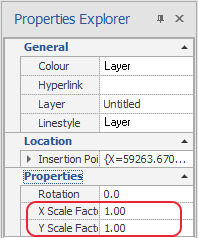
Below are the figures you need to try in both the X and Y Scale factor boxes, try all of these until the measurements match as explained above in Step 8.
X Scale Factor = 10
Y Scale Factor = 10
X Scale Factor = 100
Y Scale Factor = 100
X Scale Factor = 1000
Y Scale Factor = 1000
If the plan you imported is in feet and inches, use the below scale factors:
X Scale Factor = 25.4
Y Scale Factor = 25.4
(1 inch)
X Scale Factor = 304.8
Y Scale Factor = 304.8
(1 foot)
-
Now you have inserted your DWG you have 2 options:
- Explode the inserted DWG so it releases all the individual entites and layers for editing.
- Convert the DWG into a symbol which releases all the individual entites and layers for editing but keep all of the entities groupe together to make it easier to manipulate.
To explode the DWG, select it then go to MODIFY > Explode as shown below.
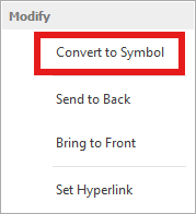
To conver the DWG to a Symbol, select the DWG then press F4 on your keyboard, a little menu will appear with the option to "Convert to Symbol" as shown below.