Creating a Gross Area Automatically
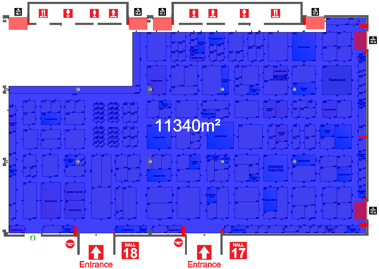
This function allows you to generate Gross Areas automatically around a selected set of stands. If you prefer to draw a Gross Area manually, please see here.
-
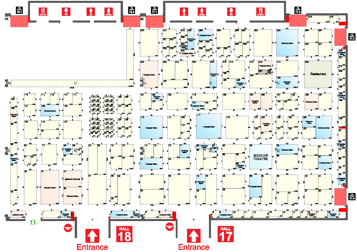
First, select the stands that need to be contained within your Gross Area.
TIP: To select all stands quickly, click the 'Select Stands' button on your Stand List, or press F3 to enter 'Select Stands Only' mode and then press CTRL+A on your keyboard.
The image below shows all stands selected:
-
With the stands selected, click the 'Create a Hall/Show Boundary Around Selected Stands' button in the toolbar.

-
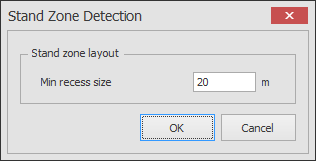
A dialog box will appear asking for a Minimum Recess Size (the default is 20).
This setting determines how tightly the gross area "hugs" the outer stands:
- Smaller numbers: Result in a tighter fit.
- Larger numbers: Result in a the boundary skipping gaps that may be within the perimeter stands.
- You may need to experiment with this value to achieve the desired visual result.
-
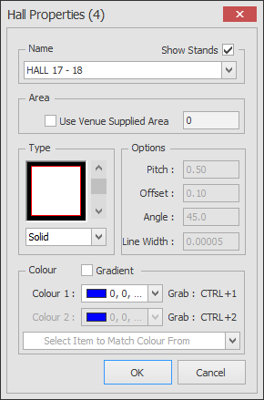
After clicking OK above, the box below will now pop up allowing you to give the Gross Area / Hall boundary a name.
At this stage you can also set the colour, this is useful if you have a multi hall show and you need to distinguish the different halls easily.
You can also set whether the stands that are within this boundary are shown on screen, this is useful when working with multi-hall shows but, for now leave this ticked, you can change this later if needed.
TIP: You can also set what stands are shown by Gross Area/Hall Boundary in individual Views.
Name:
You can either select a name from the drop down box or type your own name in. If you type a new name in, make sure its descriptive so that when you produce the floorplan figures you know what hall/show it is supposed to be.
Show Stands (tick box) - This option allows you to hide the stands that are in this particular Hall Boundary. This can be useful when multi-hall floorplans are created. You can also set this option per view for even more flexibility e.g. I can create a view called Hall 1 that does not show the stands for Hall 2 and vise-versa.
Area:
Use Venue Supplied Area - This allows you to override the automatically calculated gross area and add in a figure supplied by the venue, this then gives you accurate gross and net figures when running a report. Tick the box and then enter the relevant figure.
Type:
This allows you to choose how the Hall Boundary is shaded. The most common is Solid but you can also use Single, Double or Cross hatch lines.
Options:
- Pitch: This is only available when Single, Double or Cross hatch type is selected and specifies how large the gap is in between each hatch line.
- Offset: This is only available when the Double hatch line type is selected and specifies the gap between the 2 hatch lines.
- Angle: This is available when Solid (with Gradient ticked) or Single, Double or Cross hatch type is selected. For hatch types it lets you specify the angle of the hatch lines. For Solid with the Gradient option ticked it allows you to specify the angle of the gradient.
- Line Width: This is only available when Single, Double or Cross hatch type is selected and specifies the thickness of each hatch line.
Colour:
- Gradient (tick box): This is only available when Solid type is selected. Tick this to allow you to choose 2 colours.
- Colour 1: This is available when Solid, Single, Double or Cross hatch type is selected. Choose a colour from the drop down box or move your mouse over something on your screen and press CTRL+1 to grab the colour.
- Colour 2: This is only available when Solid type is selected and the Gradient tick box is ticked. This allows you select the 2nd colour of your gradient fill or move your mouse over something on your screen and press CTRL+2 to grab the colour.
- Select Item to Match Colour From (drop down box): If there are colours already used on your floorplan for other Hall Boundaries, Zones or Stands that you want to use on your new Hall Boundary, click this box and select as required.
-
Click OK to generate the Gross Area.
If the result is not perfect, you can use the Undo command and try again with a different recess size. For manual fine-tuning of the boundary nodes, follow the instructions here.